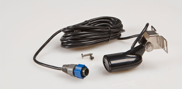
We live in an era of immediate gratification, in other words we want to hit the power button and be up and running within seconds. Unfortunately you are going to come across certain items in your life that very rarely offer this immediate gratification feature, and one of them is your sonar. But fortunately you will learn some little tricks of the trade in this article that will turn you into an installation and setup guru in no time at all. First of all is deciding which transducer is suitable to your application. In the HDS range for example you have several choices, the standard transom mount skimmer HST-WSBL, the trolling motor mount PDT-WBL which has exactly the same piezoelectric components or ‘guts’ as the HST-WSBL, the P66 and P79 by Airmar. The P66 is recommended on craft where the standard skimmer has not produced the same results as that on conventional craft, or where the water turbulence is unusually high as it approaches the transducer surface. For in - hull installation on the dead rise (commonly known as the ‘V’) of the hull, the P79 is recommended. I personally am not a big fan of in-hull installations.
The installation instructions that come with the Lowrance systems and Airmar transducers have all the info you need to do the perfect job. So I am not going to repeat these instructions, but rather try explaining why following the instructions are so important.
Location
Your hull’s transom design will dictate where your transducer will be fitted, and in some cases the perfect setup will be nearly impossible. This is the case with the stepped transom on the typical bass boat today. Your best option here if you require sonar while on the plane will be a really good medium power through-hull transducer like the Airmar P79. Ideally you want your transducer face to run just below the planing surface of the hull. If this is impossible due to a step in the transom, and you are fitting a transom mount Structure Scan transducer, then you will be forced to fit it to the step or the jack plate. You will then be limited to idling speeds only because at any faster speed the turbulence will become too great and the transducer will ultimately come out the water and you will get no return whatsoever. Other obstacles to watch out for are getting too close to the prop wash and chines on the hull of the boat. These cause terrible interference, clutter or ringing. The last thing to watch out for are chips or deep scratches in the hull directly in front of the transducer, which will also cause a lot of ringing and loss of signal when the speed is increased.

Angle
Ever heard the saying, “Look after the pennies and the pounds will look after themselves”? Well this is certainly the case with dual frequency transducer setup. What I’m saying is that if you can get your small 20° 200kHz frequency set up correctly, then the big 60° cone of the 83kHz will automatically be setup perfectly.
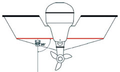
The first angle to setup correctly is ensuring that the transducer is facing perpendicular to port and starboard. You can easily achieve this by using insulation tape and marking it off on a common point on the port and starboard. Then place the top of the transducer mounting stencil parallel to the tape. I will explain a little later why this angle is just as important as the fore-aft angle.

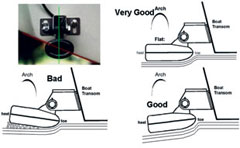
The fore-aft angle or Float Angle Correction (FAC) becomes a little trickier because of the way different boats lie in the water while idling or on the trolling motor. The easiest way to determine your boat’s angle in the water is to take note of the dirty line left on the side of the hull after a day’s fishing. Ideally your transducer should be a hair shy of right angles to this line to get a near 100% return.
“Why are these angles so important?”
Below is a typical sonar array from a transducer showing from the strongest to the weakest areas in figures 3 and 4, as well as the outer lobe areas in figure 5. Figure 4 also explains why sonars have difficulty in very shallow conditions as well as all that surface clutter in the first couple of feet on your display screen.

Okay, so the evidence presented here makes it abundantly clear how important the angle of your transducer is, but it gets worse. Remember that the sonar is actually reading the echo coming back from the object that has been pinged. So let’s say your transducer angle is out by only 8° as in Figure 6, but effectively you are in fact 16° out. And at 16° your efficiency level of your expensive investment is way below 50% of its full potential, and in most cases you won’t even see the fish at all.

Fish Arches
You are probably thinking: “Fish at last!” Fish are represented as arches on your display unit, and having a good understanding of these arches will ultimately help you target the fish a lot more accurately and efficiently.
So why is a fish represented as an arch on a fishfinder? As the cone passes over the fish, the fish is first detected in the substantially weaker area of the cone shown here as a dark blue -15dB range. As the stronger section of the cone passes directly over the fish the core colour changes accordingly from green, to yellow and ultimately deep red -0dB centre.

The next question that usually crops up is: “But why isn’t it just a flat line represented by the various strength colours?” If your boat as well as the fish directly beneath the boat were stationary, or if the fish was moving in the same direction and speed as your boat, then yes it would be represented as a line or streak rather than an arch. The arch is created by the distance to the fish being reduced as you get closer and increased again as you pass over it and start to move further away. That is why the fish arches of the narrow 20° cone of the 200kHz frequency sound wave do not have the same long ‘tails’ as that of the wide 60° cone of the 83kHz cone. As can be seen on this display of the new dual frequency Lowrance Mark-5x Pro.
Setup and Test
Before you actually get onto the water to verify if your transducer is set up perfectly, do a head unit setup. The following set up is for the HDS range.
Step 1. Select the transducer you have installed from the Installation menu.
Step 2. Turn Noise rejection and Surface clarity off
Step 3. Scroll speed Normal
Step 4. Fishing Mode Fast Trolling
Step 5. Frequency 83kHz
Step 6. Ping Speed Max
Step 7. Temperature graph and Zoom bars On
Step 8. Depth, Fish Id, Fish Id Beeps and Amplitude scope Off
Step 9. Sensitivity Auoto: 2%
Step 10. Colourline 75%
You are now ready for a water test.

For the water test you will need a common ‘H’ marker buoy, a tennis ball, medium cable tie and a large weight (just enough to pull the tennis ball down). Cable tie the tennis ball to the marker buoy line 3ft from the weight.
Only do this test in very calm conditions on a part of the dam that has a very flat bottom at about 20ft – 30ft. Once you have dropped the marker make a wide turn and do a very straight and dead slow (<3kph) approach to the marker making sure that it passes right next to the boat on the side where you have mounted the transducer.

You should see an arch similar to Figure 10 if you have a perfect setup. An arch with a longer right tail is really bad and will generally give you a poor return unless you are barely moving due to the turbulence / air bubbles created below the transducer.
If you have a Structure Scan fitted you need to make sure that the two transducers are perfectly focused on the same spot. The way to do this is with the same test you did to check your arch shapes, only now you split the screen to Structure + Sonar. The tennis ball will only appear as a very small dot due to the Structure Scan’s fore to aft beam of only 1.8°. Place your cursor directly inline with the small dot and the corresponding cross on the sonar page should line up with the centre / highest part of the arch.
Your fishfinder is now set up to its absolute optimum, and you should now start seeing a whole new world of fishing possibilities.


 Visit us our